Architecture
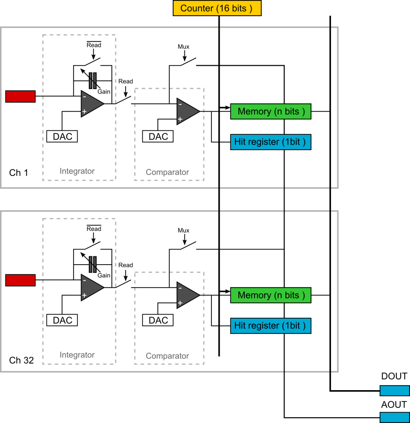
A PEPITA channel consists of a integrator with a reset and two comparators (high and low thresholds). The integrator output signal is given by:

PEPITA chip block diagram
Size |
? µm x ? µm |
Process |
XFAB 180 |
Number of channels |
32 |
Power supply |
3.3 and 1.8 V |
Operating range (beam current) |
100 pA to nA |
Power dissipation |
? |
Registers
Name |
Description |
Address |
Nb of bits |
Default value |
|---|---|---|---|---|
LECTURE_REGISTRE |
Not used at this time |
1 |
32 |
|
BIN_VCM |
Common voltage |
2 |
320 |
|
BIN_VTH_H |
High threshold |
3 |
256 |
|
BIN_VTH_L |
Low threshold |
4 |
256 |
|
MODE_ABC |
Integrator gain |
5 |
96 |
|
MODE_PEPITA |
Mutiplexed or Panic |
6 |
1 |
|
SHORT_SAMPLER |
Self explanatory |
7 |
32 |
|
ANA_ON |
Analog part on/off |
8 |
32 |
|
MULTIPLICITY |
Hitted channels |
9 |
5 |
|
SW_PEPITA |
Config in panic mode |
10 |
32 |
|
TRIM_BIAS_TRIG |
Not used at this time |
11 |
96 |
|
TRIM_RST_CONTROL |
Not used at this time |
12 |
96 |
Note
These are shift registers.
BIN_VCM
A 10-bit DAC input. It controls the common-mode voltage of input amplifier. The voltage step size is given by the following formula:
\[\Delta V = (VDAC_{Max} - VDAC_{Min}) / (2^{10} - 1)\]
Code
Value
0
\(VDAC_{Min}\)
0 < i < 1023
i * \(\Delta V\)
1023
\(VDAC_{Max}\)
BIN_VTH_H
8-bit DAC input. It sets the threshold of one of the two comparators. If the voltage at the output of the integrator is rising (due to negative input current from the detector), the rising voltage will cross this threshold. Its value is normally higher than VDD/2, for example 1.85 V if we want to set the \(\Delta V_{th}\) at 200 mV.
The voltage step size:
\[\Delta V = (VDAC_{Max} - VDAC_{Min}) / (2^{8} - 1)\]
Code
Value
0
\(VDAC_{Min}\)
0 < i < 255
i * \(\Delta V\)
255
\(VDAC_{Max}\)
BIN_VTH_L
8-bit DAC input. Its value is normally lower than VDD/2, for example 1.45 V if we want to set the \(\Delta V_{th}\) at 200 mV.
\[\Delta V = (VDAC_{MAX} - VDAC_{Min}) / (2^{8} - 1)\]
Code
Value
0
\(VDAC_{Min}\)
0 < i < 255
i * \(\Delta V\)
255
\(VDAC_{Max}\)
MODE_ABC
This sets the gain of the integrator. It selects the feedback capacitor depending on the input current.
Code |
Value |
|---|---|
0 |
2fA - 200fA |
1 |
200fA - 20pA |
2 |
2nA - 10nA |
MODE_PEPITA
When operating the ASIC in the analog multiplexed reading mode, we can read the 32 outputs one by one (depending on the three reading modes) or 8 outputs (MODE PANIC). If MODE_PEPITA is '1', mode panic is set.
Code |
Mode |
|---|---|
0 |
Norm |
1 |
Panic |
SHORT_SAMPLER
Shorts the input to the output of the sampler in case the sampler would not function as expected
Bit number |
Value for channel i |
|---|---|
i |
0 : Off 1: On |
ANA_ON
Turns on or off the analog part of a channel.
Bit number |
Value for channel i |
|---|---|
i |
0 : Off 1: On |
MULTIPLICITY
Sets the number of channels which should be "HIT" before we start reading. The code value is equal to the number of channels required.
SW_PEPITA
Channels are clustered by 4 in 8 groups. Only 1 channel in each cluster can be enabled. Channel 0 is the LSB and channel 31 is the MSB. The i th bit corresponding to the i th channel must be set to 1 to be read and the others set to 0.
Group |
Bit number i |
|---|---|
1 |
0 to 3 |
2 |
4 to 7 |
3 |
8 to 11 |
4 |
12 to 15 |
5 |
16 to 19 |
6 |
20 to 23 |
7 |
24 to 27 |
8 |
28 to 31 |