Readout
Time to Digital Converter (TDC)

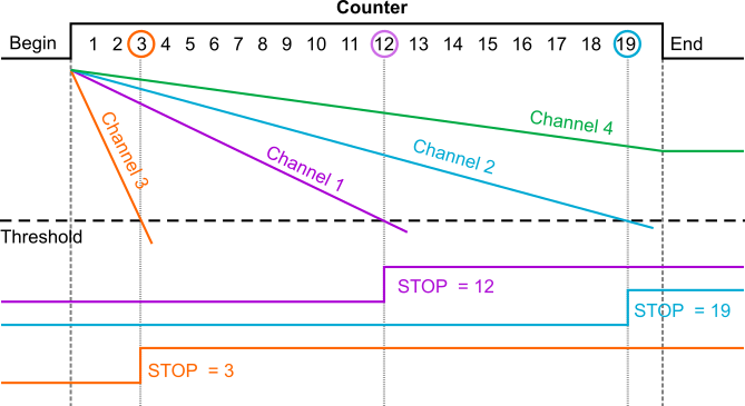
TDC principle
When a channel crosses the threshold, the state of the counter is stored locally. If a channel has no enough current to cross the threshold before the end of the measure it is lost.
The counter is a 16 bits Gray counter (1 to 65000).
Analog Multiplexed (AMUX)
The counter is stopped and currents are integrated during a tacq. Then integrator outputs are memorized using a sample and hold circuit. The readout always starts by reading the hit register which indicates channels that have crossed the threshold. Three readout modes are available:
AUTO: only memorized values in hitted channels are read.
ALL: all analog values are read.
SELECT: the user send a list of channels to read to the ASIC. This mode is useful for reading neighbor channels
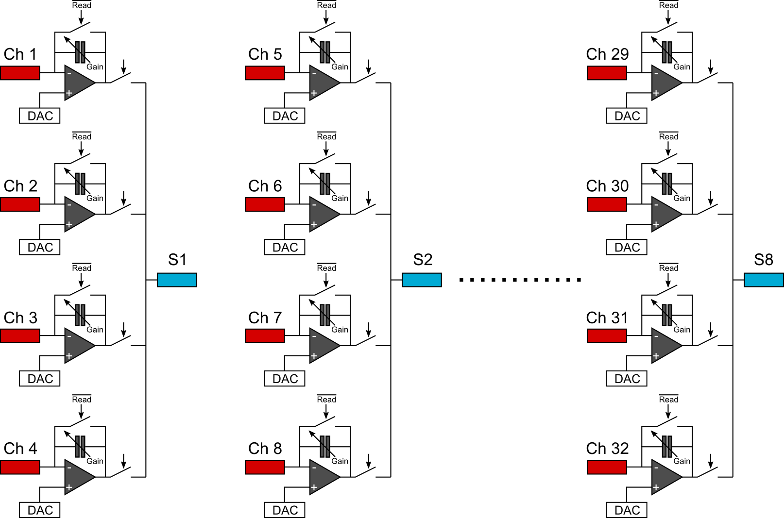
ASIC 8 channels (8CH)
This is an ASIC test mode for but it can be useful in case of trouble due to a readout problem or noise in the numerical signal. 8 integrator outputs are selected among 32 on 8 PADs. Channels are clustered by 4 and one is selected by programming to be connected in continuous (whitout need of a readout sequence) to an output PAD.
